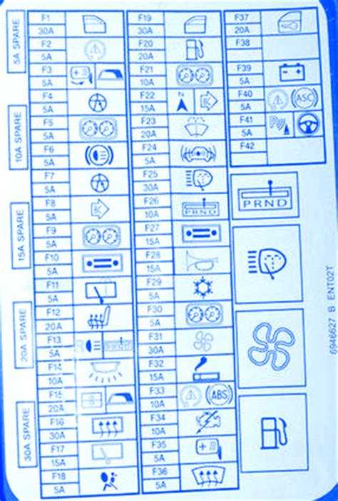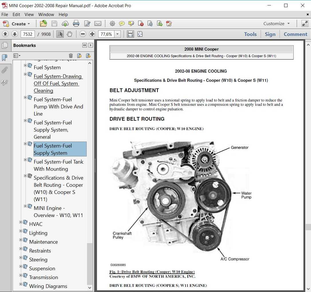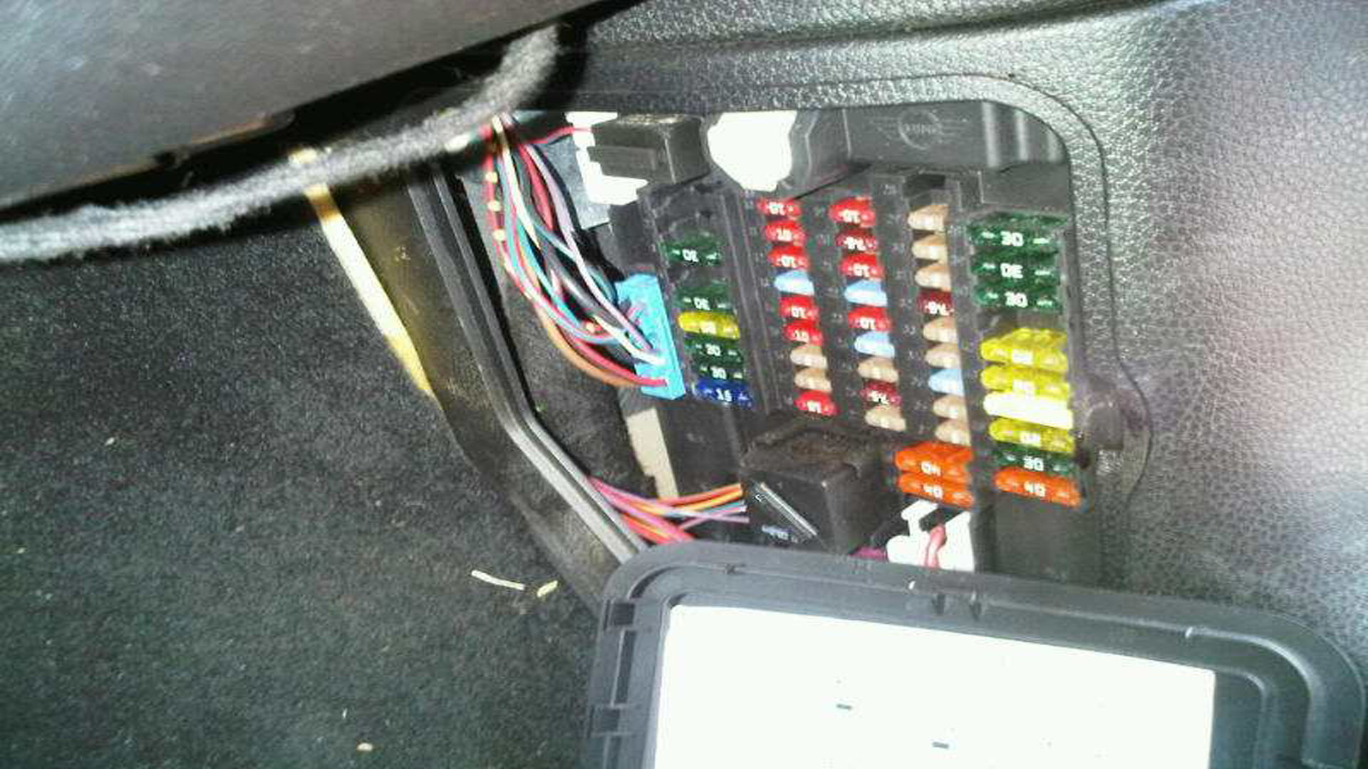
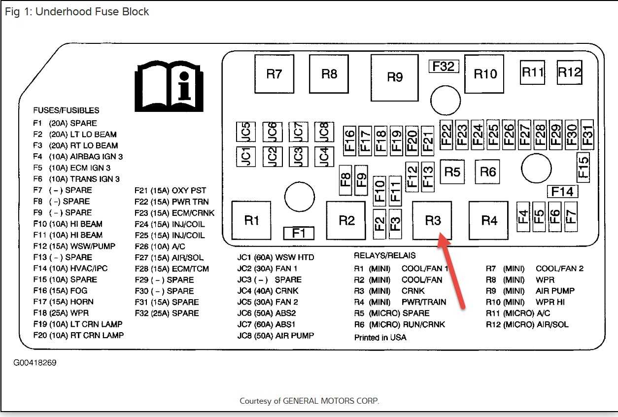
Mini Countryman Fuse Box Diagram (Glove Box)
| Fuse Number | Fuse Amp. | Protected Component |
|---|---|---|
| 30 | – | – |
| 31 | 50A | Heated Windscreen Relay |
| 32 | 40A | Body Domain Controller |
| 33 | – | – |
| 34 | 40A | Blower Output Stage |
| 35 | 50A | Body Domain Controller |
| 37 | 5A | Parking Brake Button |
| 38 | 5A | Siren with Tilt Alarm Sensor |
| 39 | 5A | Roof Function Centre (Airbag Indicator Lamp) |
| 40 | 5A | Dynamic Stability Control (DSC) |
| 41 | 5A | Instrument Cluster Control Unit |
| 42 | 5A | Remote Control Receiver (Comfort Access, Central Locking System, Tyre Pressure Control) |
| 43 | 30A | Roof Function Centre |
| 44 | 20A | Right Headlight |
| 45 | 30A/40A | Dynamic Stability Control (DSC) |
| 46 | 5A | except Cooper SE: Natural Vacuum Leak Detection |
| 46 | 10A | Cooper SE: Pressurised Fuel Tank Control Module |
| 47 | 20A | Left Headlight |
| 48 | 30A | Selective Catalytic Reduction (SCR) Control Unit |
| 49 | 5A | Electrical Exhaust Flap, Control Electronics for Electric Auxiliary Heater №2 |
| 50 | 5A | Radiator Shutter Drive Unit, Environmental Air Catalyst Sensor (except Cooper SE) |
| 51 | 5A | Base Plate Fan |
| 52 | 5A | Electrochromic Interior Rear View Mirror |
| 53 | 5A | Automatic Recirculated Air Control (AUC) Sensor |
| 54 | 5A | Electromechanical Power Steering |
| 55 | 4 | Reversing Camera, Parking Assistant |
| 56 | 5A | except Cooper SE: Longitudinal Torque DistributionCooper SE: Longitudinal Torque Distribution, Vehicle Sound Generator 1 & 2 |
| 57 | – | – |
| 58 | 10A | Steering Column Switch Cluster |
| 59 | 5A | Camera-Based Driver Assistance System |
| 60 | 5A | Optional Extra System |
| 61 | 20A | Headunit (Radio or Navigation System) |
| 62 | 5A | Interior Light, Rain Light Solar Condensation Sensor, Vanity Mirror Light, Third Row of Seats Interior Light |
| 63 | 20A | Trailer Socket |
| 64 | – | – |
| 65 | 20A | Front Cigarette Lighter (12 V Power Socket) |
| 66 | 20A | Electric Fuel Pump Control Electronics |
| 67 | 5A | Exterior Mirror (Front Passenger) |
| 68 | 5A | Touchbox, Controller (CON), USB Hub, USB Charging Socket №3 |
| 69 | 5A | Exterior Mirror (Switch Block – Driver’s Door) |
| 70 | 5A | Luggage Compartment Light, Glove Compartment Light, Rear Lid Button on Inside of Rear Lid |
| 71 | 7.5A | Instrument Cluster Control Unit |
| 72 | 5A | Fan 400W>: Electric Fan Cut-Out RelayFan >400W: Integrated Supply Module |
| 73 | 10A | Driver’s Seat Backrest width Adjustment Valve Block, Driver Lumbar Support Valve Block, Switch for Backrest width Adjustment Driver’s Seat |
| 74 | 7.5A | Petrol: Turbocharger Coolant Pump (TU) |
| 75 | 10A | Front Passenger Seat Backrest width Adjustment Valve Block, Front Passenger Lumbar Support Valve Block, Switch for Backrest width Adjustment Front Passenger |
| 76 | 10A | Diesel: Diesel Particulate Sensor |
| 77 | 10A | Nitrogen Oxide Sensor after Selective Catalytic Reduction (SCR) Catalytic Converter |
| 78 | 15A | Selective Catalytic Reduction (SCR) Control Unit |
| 79 | 5A | Base Plate, Wireless Charging Oddments Tray, Wireless Charging Oddments Tray Aerial Amplifier |
| 80 | 5A | Central Instrument, Central Information Display |
| 81 | 15A | Electronic Transmission Control |
| 82 | 5A | Selector Level |
| 83 | 7.5A | Petrol: Digital Motor Electronics |
| 84 | 5A | Clutch Module (Manual Transmission), Twin-Clutch Gearbox Control Unit, Twin-Clutch Gearbox Relay |
| 85 | 5A | Electrochromic Interior Rear View Mirror |
| 86 | – | – |
| 87 | – | – |
| 88 | – | – |
| 89 | – | – |
| 90 | – | – |
| 91 | 15A | Active Sound Design |
| 92 | 10A | Optional Extra System |
| 93 | – | – |
| 94 | – | – |
| 95 | 30A | Front Passenger Side Seat Adjustment Switch Block |
| 96 | 10A | Boot Lid/Tailgate Lock |
| 97 | – | – |
| 98 | 5A | Preparation of Tall Function |
| 99 | – | – |
| 100 | 5A | Cooper SE: High-Voltage Battery Unit |
| 101 | 5A | ID Reader, Car Sharing Module (CSM) |
| 102 | – | – |
| 103 | 20A | Right Headlight |
| 104 | 20A | Left Headlight |
| 105 | – | – |
| 106 | – | – |
| 107 | 40A | 2017: Automatic Luggage Compartment Lid Actuation2018-2022: Tailgate Function Module |
| 108 | – | – |
| 109 | 5A | Bi-Stable Relay |
| 110 | 5A | Bi-Stable Relay |
| 111 | 5A | Bi-Stable Relay |
| 112 | – | – |
| 113 | – | – |
| 114 | – | – |
| 115 | 5A | Cooper SE: Convenience Charging Electronics |
| 116 | – | – |
| 117 | – | – |
| 118 | – | – |
| 119 | 20A | Trailer Module, Trailer Socket |
| 120 | 20A | Trailer Module, Trailer Socket |
| 121 | 7.5A | USB Charging Socket №4 (Rear) |
| 122 | 5A | Safety Battery Terminal Gas Generator |
| 123 | 5A | Electrical A/C Compressor, Electric Auxiliary Heater |
| 124 | 10A | Cooper SE: Electric-Machine Electronics |
| 125 | – | – |
| 126 | – | – |
| 127 | 30A | Driver’s Seat Heating Electronics (Basic Version), Driver’s Seat Module (High Version) |
| 128 | 30A | Front Passenger Seat Heating Electronics |
| 129 | 30A | HiFi Amplifier |
| 130 | 10A | Cooper SE: Coolant Pump 2 in Low-Temperature Coolant Circuit |
| 131 | 30A | Cooper SE: Transmission Oil Pump, Longitudinal Torque Distribution except Cooper SE: Longitudinal Torque Distribution |
| 132 | 20A | 12V Power Socket №1, 12V Power Socket №2 (2017-2018), 12V Power Socket №4 (Luggage) |
Mini — Video tutorial
Model: Mini Mini
R57, R56, R55
— Years 2007-2014
Part: Fuse box
Operation: Where to find fuses in a Mini Cooper
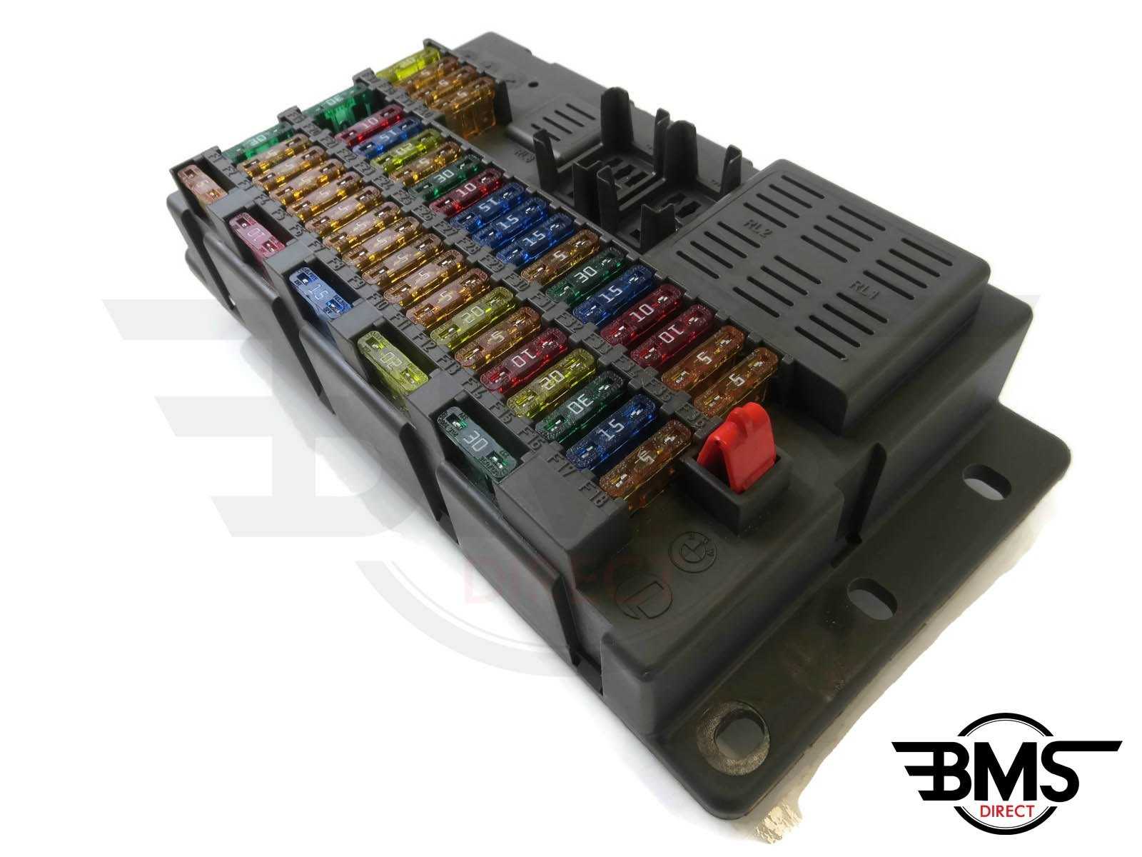
Fuses are a fundamental part of a car’s electronics. In this video we will go to see where to find them in a Mini Cooper. Taking the driver’s seat as a reference, next to the pedals towards the outside of the car you can see a door (in the video, with a car with an English guide, you will see everything reversed). Open it with the help of a screwdriver. Once this is done you will find the fuse panel in front of you. In the lid that you have removed, on the inside, it is possible to have the mapping to identify the function of each of them. There is also another compartment, with other fuses; to find it you need to open the hood; once opened, you will see a box, the last one at the top right. Inside you will find other fuses and, also in this case, inside the cover that you will remove there will be a diagram with the indications of the function of each of them and of the relays.
Posted on 29 November 2021 by ScegliAuto
Other guides that may interest you
- Mini Mini — Other Do-It-Yourself Maintenance and Repair
-
Dent
— Maintenance and repair on other vehicles- Vari Altri Vari — How to fix dents on the car’s bodywork.
- Vari Altri Vari — One way to remove rust from the bodywork
- See All
-
Door
— Maintenance and repair on other vehicles- Mini Mini — How to remove the boot lid of the Mini Cooper
- Mini Mini — How to open the hood of the Mini One
- See All
-
Seat
— Maintenance and repair on other vehicles- Mini Mini — How do you remove the front seat of the Mini Cooper?
- Mini Mini — How do you remove the front seat of the Mini R53?
- See All
More videos
-
Reset service on lancia Ypsilon
Posted on 4 December 2023 by ScegliAuto
-
How to reset the tire warning light on BMW 1 Series
Posted on 2 December 2023 by ScegliAuto
-
Reset maintenance on Fiat Doblo
Posted on 2 December 2023 by ScegliAuto
-
Battery replacement of a Mercedes A-Class
Posted on 30 November 2023 by ScegliAuto
-
How to open the door of the Golf 7 with a dead key battery
Posted on 30 November 2023 by ScegliAuto
-
Replacing the remote control battery on BMW X1
Posted on 30 November 2023 by ScegliAuto
-
Disassembly of the drive shaft on Fiat Panda
Posted on 28 November 2023 by ScegliAuto
-
How to reset the tire pressure warning light on Citroen C3
Posted on 27 November 2023 by ScegliAuto
-
Disassembly of the power panel BMW Z3
Posted on 26 November 2023 by ScegliAuto
-
How to remove the rear light of a Ford kuga
Posted on 26 November 2023 by ScegliAuto
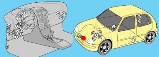
K12
Locations
Diagram
Appointment
| 1 | Air conditioning control unit – behind the heater control panel |
| 2 | Sunlight sensor (air conditioning system) |
| 3 | Intake air temperature sensor (air conditioning / heater) |
| 4 | Shock sensor (SRS) |
| 5 | Impact sensor, driver’s side – under the seat |
| 6 | Crash sensor, passenger side – under the seat |
| 7 | Anti-theft control unit oh – if fitted |
| 8 | Accumulator battery |
| 9 | Central locking relay – “keyless entry”, if any |
| 10 | Diagnostic connector (DLC) |
| 11 | Coolant Heater Relay – Diesel |
| 12 | Fuse and relay box, engine compartment 1 |
| 13 | Fuse and relay box, engine compartment 2 |
| 14 | Fuse and relay box, engine compartment Z |
| 15 | Fuse and relay box, engine compartment 4 – diesel engine |
| 16 | Fuse and relay box dashboard |
| 17 | Additional fuse (Main250A) – battery |
| 18 | Heater fan motor resistor – in the heater fan motor |
| 19 | Sound signal – behind the radiator grille |
| 21 | Immobilizer transponder – ignition lock |
| 24 | Multifunctional control unit 2 – functions: central locking, power windows, alarm, rear window defogger, immobilizer control unit, direction indicators, interior lamps, fog light, rear window cleaner, windshield washer cleaner |
| 25 | Navigation control unit – in the audio system unit (if any) |
| 26 | Ambient temperature sensor |
| 27 | Start inhibit switch – at checkpoint |
| 28 | Power steering control unit |
| 29 | SRS electronic control unit |
| 30 | Electronic gearbox control unit |
| 31 | Trip computer |
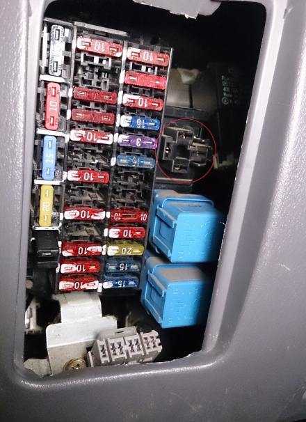
Passenger compartment
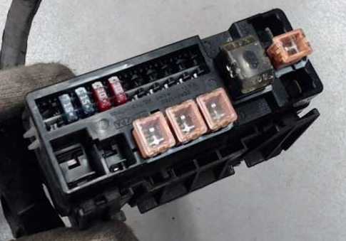
Located in the dashboard next to the steering rack. This unit is closed with a protective cover, on the back of which there will be an up-to-date description.
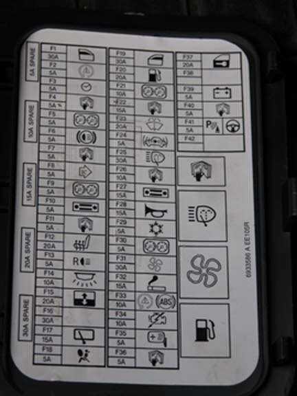
The photo
Diagram
Designation
| 1 | Relay accessories |
| 2 | Heater blower motor relay |
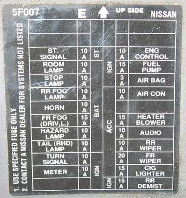
| F1 | (15A) Windshield wiper |
| F2 | (10A) Instrument cluster indicators |
| F3 | (10A) SRS system |
| F4 | (10A) Multifunction control module 1, diagnostic socket |
| F5 | (10A) Brake light switch (brake pedal position sensor), ABS, brake lights |
| F6 | (10A) Central locking, anti-theft system, air conditioning system |
| F7 | (10A) Multifunction control module 1 |
| F8 | (10A) Indicators in instrument cluster, diagnostic connector (DLC) |
| F9 | (15A) Heater air conditioner |
| F10 | (15A) Heater air conditioner |
| F11 | (15A) nissan micro cigarette lighter fuse |
| F12 | (10A) Audio system, navigation system, anti-theft system, electric door mirrors, trip computer |
| F13 | (10A) Heated rear window |
| F14 | (10A) Daytime running lamps |
| F15 | (10A) Heated seats |
| F16 | (10A) Air conditioner |
| F17 | (10A) Anti-theft system, central locking, interior lamps |
Box with relay behind the headlight
The photo
Diagram and pinout
Fuse
| F31 | – |
| F32 | – |
| F33 | (10A) RH headlamp – high beam, daytime running light system – if equipped |
| F34 | (10A) High beam – left headlamp, daytime lighting system – if equipped |
| F35 | (10A) Right tailgate |
| F36 | (10A) Rear left-hand side marker |
| F37 | – |
| F38 | (20A) Windshield wiper |
| F39 | (15A) Low beam – left headlamp, daytime lighting system – if equipped |
| F40 | (15A) Dipped beam – right headlamp, daytime lighting system – if equipped, headlight range control |
| F41 | (10A) A / C relay |
| F42 | – |
| F43 | – |
| F44 | – |
| F45 | (15A) Heated rear window relay |
| F46 | (15A) Heated rear window relay |
| F47 | (15A) Fuel pump relay |
| F48 | (10A) Transmission control module (ECM) |
| F49 | (10A) Anti lock brake system (ABS) |
| F50 | (10A) Start inhibit switch |
| F51 | (20A) Throttle control module relay |
| F52 | (20A) Engine management |
| F53 | (10A) Heated oxygen sensors |
| F54 | (10A) Injectors |
| F55 | (20A) Fog lights |
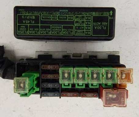
Additional box
Box 1
Diagram
Assignment
| 1 | Horn relay |
| F21 | – |
| F22 | – |
| F23 | – |
| F24 | (15A) Audio system, navigation system |
| F25 | (10A) Horn |
| F26 | (10A) Generator |
| F27 | (10A) Daytime lighting system – if equipped |
| F28 | (10A) – |
| F29 | (40A) ABS control module |
| F30 | (40A) Cooling fan motor relay |
| F31 | (40A) Ignition switch |
| F32 | (40A) Coolant heater |
| F33 | (40A) Multifunction control module 1 |
| F34 | (30A) ABS electronic board |
| F35 | (30A) Headlamp washer pump relay |
| F36 | (60A) ABS electronic control unit |
Box 2
High Power Fuse Box Diagram
Designation
- A – 250A Main fuse
- B – 80A ABS electronic board
- C – 80A Multifunctional control unit 1
- D – 60A Fuse / Relay Box – Engine Compartment 1 (F45-F46), (F51-F52), Main Ignition Circuit Relay
- E – 80A Fuse / Relay Box – Instrument Panel (F5-F8), (F14), (F17), Auxiliary Relay, Heater Blower Motor Relay
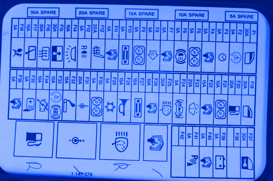
K11
Locations
Diagram
Designation
| 1 | Side impact sensor (SRS), driver’s side |
| 2 | Side impact sensor (SRS), passenger side |
| 3 | Audible Warning / Buzzer – Instrument Cluster |
| 4 | Accumulator battery |
| 5 | Central locking control unit |
| 6 | Central locking signal control unit |
| 7 | Diagnostic connector (DLC), 14-pin |
| 8 | Diagnostic connector, 16-pin |
| 9 | Daytime Lighting Control Unit – If Equipped |
| 10 | Fog lamp relay |
| 11 | Fuel Pump Relay – Lower Right Bezel |
| 12 | Fuse / relay box dashboard |
| 13 | Fuse / relay box, engine compartment 1 |
| 14 | Fuse / Relay Box, Engine Compartment 2 – Petrol |
| 15 | Fuse / Relay Box, Engine Compartment 3 – Diesel |
| 16 | Headlight Washer Delay Relay – If Equipped |
| 17 | Heated rear window relay, if equipped – C-pillar |
| 18 | Heater blower motor relay |
| 19 | Heater blower motor resistor |
| 20 | Beep 1 |
| 21 | Beep 2 |
| 22 | Horn relay |
| 23 | Relay for auxiliary ignition circuits |
| 24 | Relay for main ignition circuits |
| 25 | Electronic immobilizer control unit |
| 26 | Turn signal interrupter relay |
| 27 | Rear wiper motor relay – C-pillar |
| 28 | SRS electronic control unit |
| 29 | Electronic gearbox control unit |
| 30 | Vehicle speed sensor, type 1 – gearbox |
| 31 | Vehicle speed sensor, type 2 – instrument cluster |
| 32 | Windshield wiper motor relay |
Passenger compartment
Located in the dashboard.
Type 1
Diagram
Designation
| F1 | (20 A) Air conditioner – heater fan motor |
| F2 | – |
| F3 | (10A / 20A) Rear window heater switch, rear window heater relay |
| F4 | (10A) Horn relay |
| F5 | (15A) Fog lamp relay |
| F6 | (10A) A / C system, start inhibit switch |
| F7 | (7.5A) Central locking, idle speed control (ISC) relay – with automatic transmission, diagnostic socket |
| F8 | (10A) Heated rear window relay – if equipped, central locking, central locking signal control unit, daylight control unit – if equipped, start inhibit switch (“PVN”), reversing lights |
| F9 | (15A) Rear window washer wiper |
| F10 | (15A) Audio system |
| F11 | (7.5A) Alarm switch |
| F12 | (7.5A) ABS electronic control unit |
| F13 | (15A) Cigarette lighter fuse |
| F14 | (10A) Brake lights, ABS |
| F15 | (10A) Hazard switch |
| F16 | (10A) Transmission control module (ECM) |
| F17 | (15A) Fuel pump relay |
| F18 | (10A) Heated seats |
| F19 | (20A) Windshield wiper motor, windshield wiper motor relay |
| F20 | (7.5A) Engine management system, immobilizer control unit |
| F21 | – |
| F22 | (10A) SRS control module |
| F23 | (10A) Windshield washer cleaner |
| F24 | (10A) E / m fuel cut-off valve – Diesel, interior lighting lamps, instrument cluster, audio system, electronic gearbox control unit, immobilizer, central locking signal control unit |
| F25 | (10A) Glow plug control unit – Diesel, electric recirculation valve or EGR valve – Diesel, immobilizer, heated oxygen sensor, idle air bypass valve |
| F26 | (7.5A) Start inhibit switch relay – with automatic transmission, engine management system |
| F27 | – |
| F28 | – |
| F29 | (15A) Headlamp washer delay relay |
Type 2
The photo
Check the diagram against your description on the back of the cover.
Designation
- 10A Starter / signal
- 10A Interior lighting
- 10A Stop lamps singala
- 10A Fog lights
- 10A Signal
- 15A Fog lights
- 10A Alarm
- 10A Rear lights
- 10A Siglals of turns
- 10A Dashboard
- 10A Engine
- 15A Fuel pump
- 3A Fuel pump
- 10A Air conditioner
- 15A Heater fan
- 10A Audio system
- 10A Rear wiper
- 20A Front wiper
- 10A Cigarette lighter
- 10A Fog lights
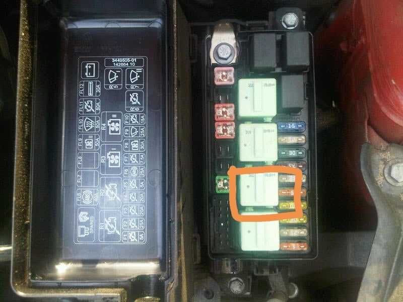
Engine compartment
Type 1
The photo
Diagram
Circuits protected
| F1 | (30A) Glow plug control module – diesel |
| F2 | – |
| F3 | (10A) Rear dimensions |
| F4 | (15A) RH headlight |
| F5 | (15A) LH headlamp |
| F6 | (25A) Power windows, central locking control module |
| F7 | (15A) Spare |
| F8 | – |
| F9 | (25A) Cooling fan motor |
| F10 | (10A) Spare |
| F11 | (15A) Air conditioner |
| F12 | (30A) Anti-lock braking system (ABS) |
| F13 | (30A) Ignition switch |
| F14 | (25A) Engine management |
| F15 | (65A) Battery power distribution |
Type 2
The photo
Diagram

Appointment
| F1 | (40A) ABS control module |
| F2 | (30A) Ignition switch |
| F3 | (40A) ABS control module |
| F4 | (80A) Battery power distribution |
| F5 | (30A) Cooling fan motor |
| F6 | (30A) Power windows, central locking control module |
| F7 | (30A) Engine management |
| F8 | – |
| F9 | (60A) Glow plug control module – diesel |
| F10 | – |
| F11 | – |
| F12 | – |
| F13 | – |
| F14 | – |
| F15 | (10A) Generator |
| F16 | (10A) Rear dimensions |
| F17 | (15A) LH headlamp |
| F18 | (15A) RH headlight |
| F19 | (15A) Air conditioner |
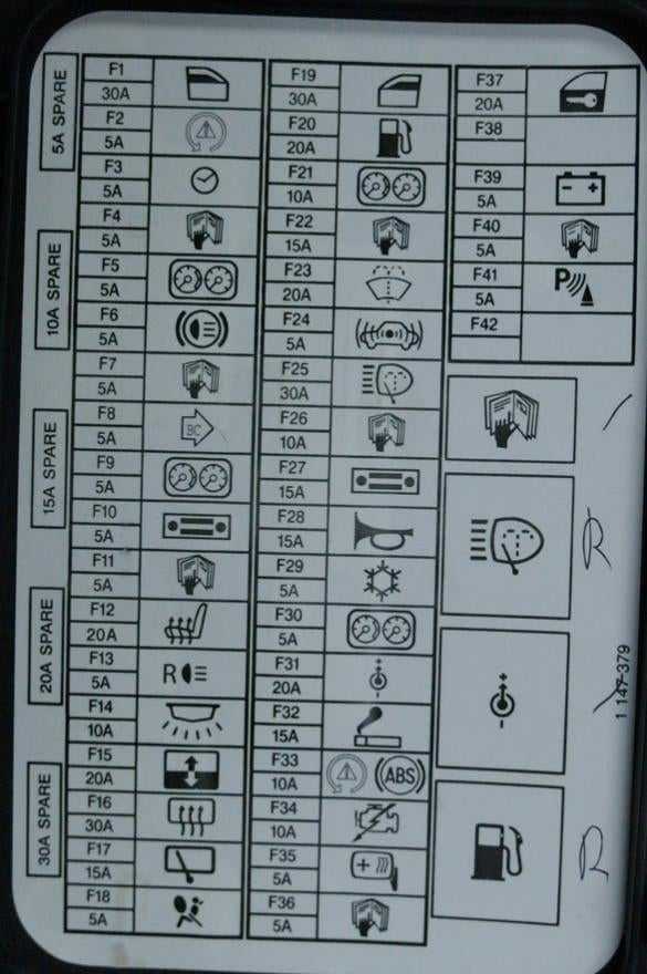
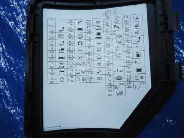
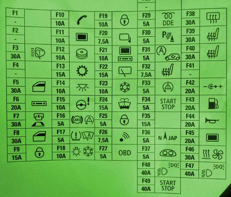
Mini Countryman Fuse Box Diagram (Body Domain Controller)
| Fuse Number | Fuse Amp. | Protected Component |
|---|---|---|
| 1 | 30A | Passenger Power Window |
| 2 | 30A | Rear Driver’s Side Power Window |
| 3 | 20A | Front Passenger Door Lock |
| 4 | 30A | Driver Power Window |
| 5 | 30A | Rear Window Defogger |
| 6 | 30A | Rear Passenger Side Power Window |
| 7 | 20A | Driver’s Door Lock |
| 8 | – | – |
| 9 | 5A | Light Operating Unit, Steering Column Switch Cluster, Driver Assistance System Operating Facility with Hazard Warning Switch |
| 10 | 7.5A | Diagnosis Socket |
| 11 | 7.5A | Heating/Air Conditioning System, Tailgate Function Module |
| 12 | 5A | Evaluation Electronics for Contact-Free Tailgate Opening, Telematic Communication Box, Electronic Outer Door Handle Module (Driver/Passenger) |
| 13 | 15A | Horn |
| 14 | 15A | Rear Wiper & Washer |
Note: The vehicle manufacturer recommends that you have a dealer’s service center or another qualified service center or repair shop replace the fuses. Additional fuse boxes are located in the vehicle. In the case of a malfunction, contact a dealer’s service center or another qualified service center or repair shop.
Tom Smith
Tom Smith is a passionate car mechanic and automotive enthusiast, specializing in the intricate world of car fuse boxes. With years of hands-on experience under the hood, he has earned a reputation as a reliable expert in his field. As the founder and content creator of the popular blog website ‘carsfuse.com,’ Tom has dedicated himself to sharing his extensive knowledge of car fuse boxes and electrical systems with the world.