
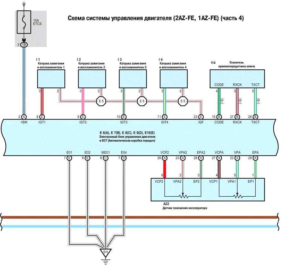
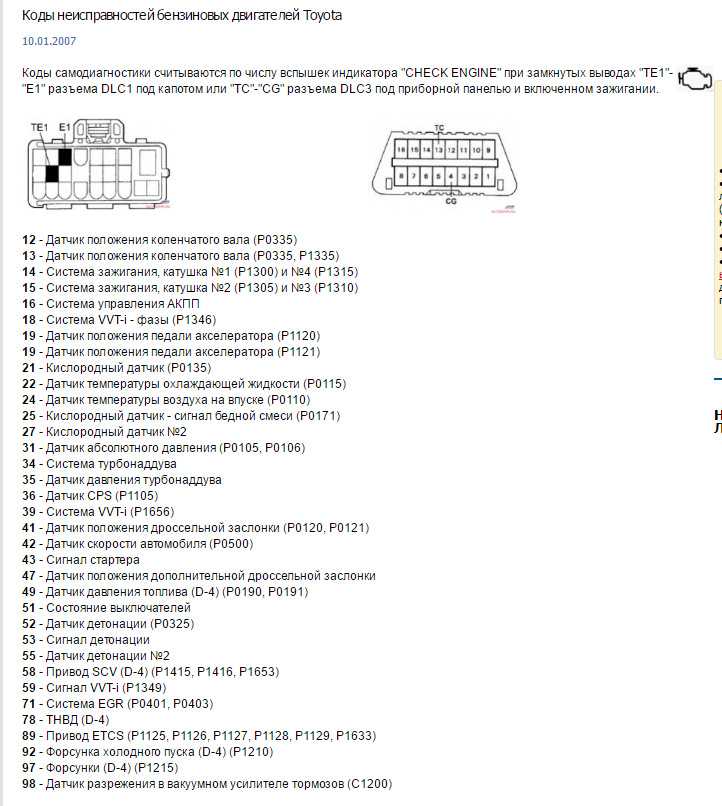
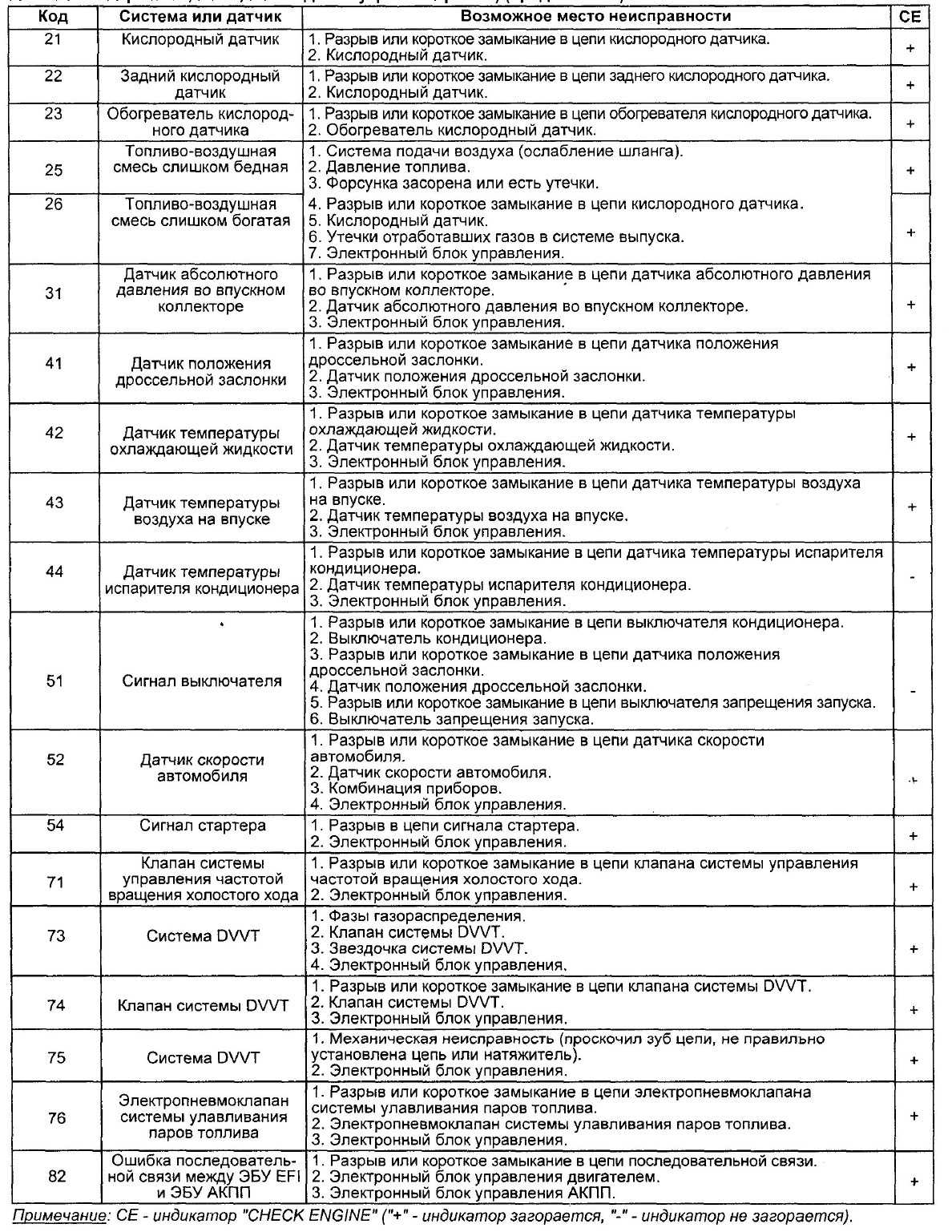
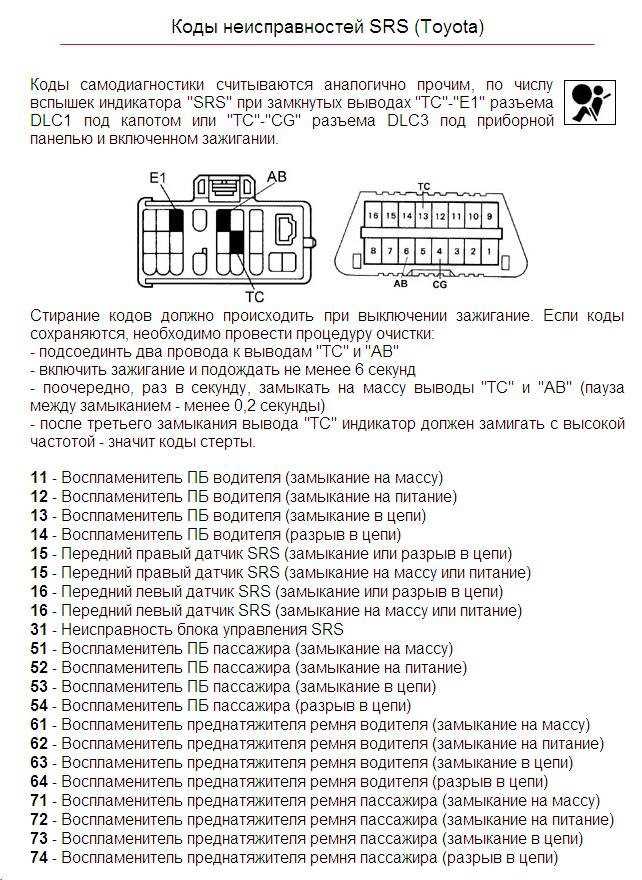
MONITOR DESCRIPTION
-
P1271 (Open or short in pressure discharge valve circuit):This DTC will be set if there is no valve opening confirmation (IJf) signal sent from the EDU to the ECM, if the ECM has commanded the EDU to open the pressure discharge valve. This DTC refers to an open or short in the pressure discharge valve circuit, not a malfunction that includes a valve that is stuck open or closed.The EDU monitors the current supplied to the pressure discharge valve to verify that the current flows into the valve. If the current exceeds the specified level, the EDU interprets this as the IJf signal is low. If this DTC is present, the ECM enters the fail-safe mode and limits engine power. The fail-safe mode continues until the ignition switch is turned off.
- P1272 (Closed malfunction of the pressure discharge valve):The pressure discharge valve will open and discharge the internal fuel pressure from the common rail to the fuel tank when the ignition switch is turned off. In this event, the ECM compares the actual drop rate of the internal fuel pressure and the target drop rate. If the ECM judges that the actual drop rate is smaller than the target, the ECM then judges that the valve is stuck closed and sets this DTC. This DTC will be stored if the internal fuel pressure does not drop to the target after the ignition switch has been turned off.If this DTC is present, the ECM enters a fail-safe mode and limits engine power. The fail-safe mode continues until the ignition switch is turned off.
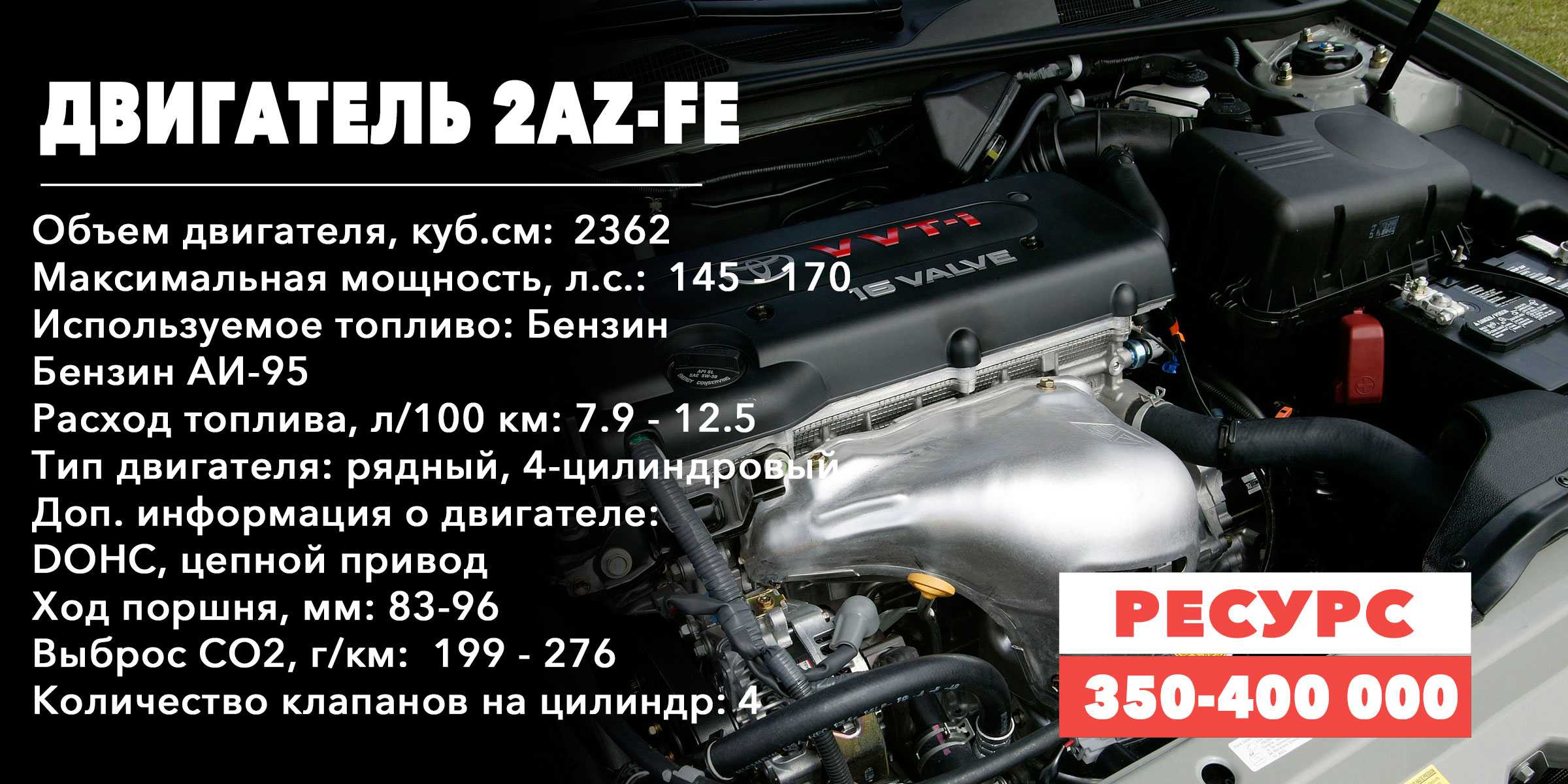
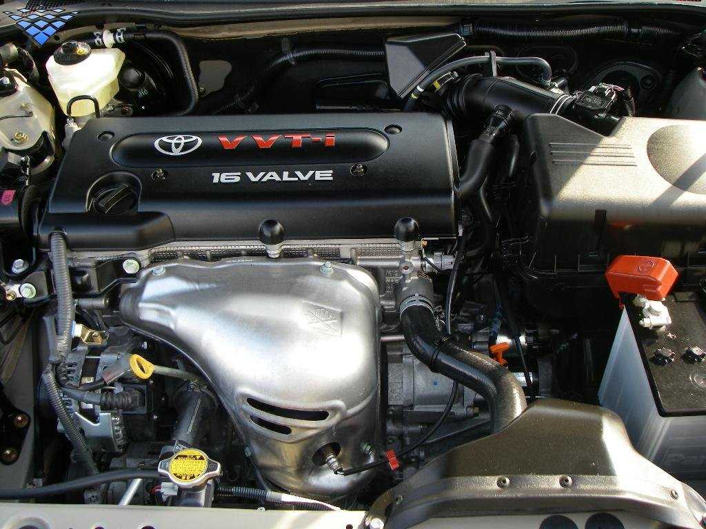
Toyota Camry 2006-2011 2AZ-FE Service Manual
| Title | File Size | Download Link |
| 1 Toyota Camry 2AZ-FE all service manual.rar | 104.9Mb | Download |
| 2 Toyota Camry 2006-2011 SRS service manual.rar | 10.4Mb | Download |
| Air Conditioning system.pdf | 17.9Mb | Download |
| Anti-Lock Brake System.pdf | 23.5Mb | Download |
| Audio and Visual system.pdf | 8.2Mb | Download |
| Axle system.pdf | 1.7Mb | Download |
| Body Repair Manual.pdf | 12.9Mb | Download |
| CAN Communication system.pdf | 4.4Mb | Download |
| Charging.pdf | 1.9Mb | Download |
| Clutch system.pdf | 2.4Mb | Download |
| Cooling.pdf | 2.6Mb | Download |
| Cruise Control system.pdf | 1.4Mb | Download |
| Drive Shaft system.pdf | 2.6Mb | Download |
| E351 Manual transaxle.pdf | 7.2Mb | Download |
| Emission Control.pdf | 1.8Mb | Download |
| Engine Control System.pdf | 11.2Mb | Download |
| Engine Hood/Door.pdf | 10.4Mb | Download |
| Engine Immobiliser (Smart Key system).pdf | 2.7Mb | Download |
| Engine Mechanical.pdf | 16.3Mb | Download |
| Exterior.pdf | 6.8Mb | Download |
| Fluid Specs.pdf | 41.8kb | Download |
| Fuel system.pdf | 3.9Mb | Download |
| Garage Door.pdf | 462.5kb | Download |
| General Information.pdf | 8.2Mb | Download |
| Ignition system.pdf | 715.8kb | Download |
| Maintenance.pdf | 79.8kb | Download |
| Owners Manual.pdf | 7.5Mb | Download |
| Power Door Lock Control System.pdf | 7.5Mb | Download |
| Service Specifications.pdf | 546.7kb | Download |
| Wire Harness Repair.pdf | 4.9Mb | Download |
What Does Toyota Camry Code P0101 Mean?
- Toyota Camry P0101 definition: Mass Air Flow (MAF) Circuit/Performance Malfunction
- Issue Severity: MODERATE – Extended driving with this code can cause internal engine damage.
- Repair Urgency: Get this code fixed as soon as possible to avoid internal engine failure.
- Diagnosis: Code P0101 does not pose any danger to the driver and will not prevent the vehicle from running. However, it will cause an increase in fuel consumption and rough operation. Sustained driving can lead to internal engine failure.
The mass air flow (MAF) sensor measures the amount of air entering the engine. Check engine light code P0101 is set when the measurement of air entering the engine by the mass air flow sensor is outside of the manufacturer’s specified range.
DIY Steps to Diagnose Toyota Camry Code P0101
Engine code P0101 could be caused by a number of things, including a dirty air filter, mass air flow sensor, catalytic converter, and more. If you’d like to try to fix code P0101 at home without throwing money at parts, you’ll want to follow the steps below for proper diagnosis. Keep in mind this is an intermediate-level diagnosis and repair and not recommended for beginners. Diagnosis beyond oil level and condition requires more specialized equipment beyond what the FIXD Sensor can provide and it can be a time and labor-intensive process for inexperienced DIYers.
DIY difficulty level: Intermediate
This repair requires mechanical knowledge and is not recommended for beginners.
Tools/parts needed:
- FIXD
- Screwdriver or basic socket set to remove the air intake snorkel
- Mass air flow sensor cleaner
STEP 1: CHECK THE AIR FILTER.
Locate your air intake box that houses your air filter. Open the air intake box using the required tools for your vehicle. Ensure the air filter is seated properly and is clean. Reseat the air filter if it is not seated properly, and replace the air filter if it is dirty. This may be as much as you need to fix P0101, however, we recommend completing step 2 as well. It is not difficult or expensive and may improve performance.
STEP 2: CLEAN THE MASS AIR FLOW SENSOR.
Remove the wiring harness from the mass air flow sensor and remove the air intake snorkel from the air intake box. Use mass air flow sensor cleaner (DO NOT SUBSTITUTE ANY OTHER KIND OF CLEANER) to clean out the MAF sensor. Do this by spraying each side of the MAF sensor for 3-5 seconds, waiting 10 seconds, and then spraying it again for 3-5 seconds. Do not wipe it. The MAF sensor hot wires are very sensitive, and MAF sensor cleaner cleans and dries very quickly. Reconnect the air intake snorkel, close the air intake box, and reconnect the MAF sensor harness. Clear the check engine light code using the FIXD app and complete several drive cycles to ensure this was the correct fix.
STEP 3: CHECK FOR VACUUM LEAKS.
If your check engine light comes back on with diagnostic trouble code P0101, examine the air intake system for vacuum leaks.
STEP 4: CHECK THE EXHAUST.
If no vacuum leaks are found, the problem is likely a restriction in your exhaust. This could be a clogged catalytic converter, or physical damage to the exhaust itself, causing a restriction that prevents exhaust gases from flowing out of the engine smoothly.
Причины кода P0031 Toyota?
Если после того как, ошибка была сброшена она появляется вновь, то проблема находится в первом верхнем лямбда -зонде. В датчике может выйти из строя подогреватель, он может иметь плохой (окисленный) контакт, неисправный 12-вольтовый вход или проблему в разъеме. Очень редко, но источником ошибки бывает неисправность блока управления двигателем Toyota.
Причины ошибки:
‘);
instant= new adsenseLoader( ‘#quads-ad4-place’, {
onLoad: function( ad ){
if (ad.classList.contains(«quads-ll»)) {
ad.classList.remove(«quads-ll»);
}
}
});
}if ( quads_screen_width >= 1024 && quads_screen_width
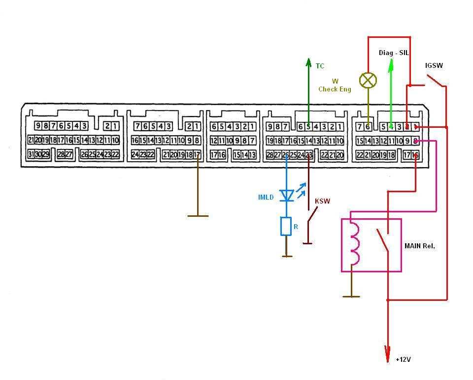
INSPECTION PROCEDURE
- ПРИМЕЧАНИЕ:
- After replacing the ECM, the new ECM needs registration (see page ) and initialization (see page ).
- УКАЗАНИЕ:
- After completing repairs, confirm that P1271 and/or P1272 does not recur.
- If P0200 and P1271 are present simultaneously, there is an open in the INJF wire harness between the EDU and ECM, or there is an open in the wire harness for both injector and pressure discharge valve.
| 1.READ OUTPUT DTC |
-
Connect the intelligent tester to the DLC3.
-
Turn the ignition switch on (IG) and turn the tester on.
-
Enter the following menus: Powertrain / Engine and ECT / DTC.
-
Read DTCs.
- Result:
-
Display (DTC Output) Proceed to Only P1271, P1271 and P1272 A P1272 only B
|
|
||||
| A | |
| 2.INSPECT PRESSURE DISCHARGE VALVE |
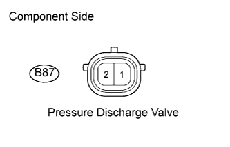 |
Disconnect the B87 pressure discharge valve connector.
-
Measure the resistance of the terminals of the pressure discharge valve.
- Standard resistance:
-
Tester Connection Condition Specified Condition B87-1 — B87-2 20°C (68°F) 0.85 to 1.05 Ω
-
Reconnect the pressure discharge valve connector.
|
|
||||
| OK | |
| 3.CHECK WIRE HARNESS (EDU — PRESSURE DISCHARGE VALVE) |
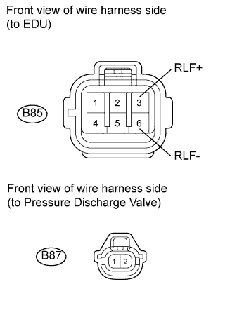 |
Disconnect the B85 EDU connector.
-
Disconnect the B87 pressure discharge valve connector.
-
Measure the resistance of the wire harness side connectors.
- Standard resistance:
-
Tester Connection Specified Condition B85-3 (RLF+) — B87-2 Below 1 Ω B85-6 (RLF-) — B87-1 Below 1 Ω B85-3 (RLF+) or B87-2 — Body ground 10 kΩ or higher B85-6 (RLF-) or B87-1 — Body ground 10 kΩ or higher
-
Reconnect the EDU connector.
-
Reconnect the pressure discharge valve connector.
|
|
||||
| OK | |
| 4.CHECK HARNESS AND CONNECTOR (EDU — ECM) |
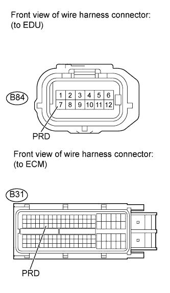 |
Disconnect the B84 EDU connector.
-
Disconnect the B31 ECM connector.
-
Measure the resistance of the wire harness side connectors.
- Standard resistance:
-
Tester Connection Condition Specified Condition B84-7 (PRD) — B31-52 (PRD) Always Below 1 Ω B84-7 (PRD) or B31-52 (PRD) — Body ground Always 10 kΩ or higher
-
Reconnect the EDU connector.
-
Reconnect the ECM connector.
|
|
||||
| OK | |
| 5.CHECK EDU (POWER SOURCE CIRCUIT) |
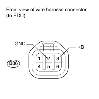 |
Disconnect the EDU connectors.
-
Turn the ignition switch on (IG).
-
Measure the voltage of the specified terminals of each EDU wire harness side connector.
- Standard voltage:
-
Tester Connection Condition Specified Condition B86-3 (+B) — B86-2 (GND) Ignition switch on (IG) 9 to 14 V
-
Reconnect the EDU connectors.
|
|
||||
| OK | |
| 6.REPLACE EDU |
-
Replace the EDU (See page ).
| NEXT | |
| 7.CHECK WHETHER DTC OUTPUT RECURS |
-
Connect the intelligent tester to the DLC3.
-
Turn the ignition switch on (IG) and turn the tester on.
-
Clear DTCs (See page ).
-
Start the engine and drive the vehicle for approximately 15 minutes.
-
Enter the following menus: Powertrain / Engine and ECT / DTC.
-
Read the DTCs.
- Result:
-
Display (DTC Output) Proceed to P1271 and/or P1272 A No output B
|
|
||||
| A | |
|
| 8.REPLACE COMMON RAIL ASSEMBLY |
-
Replace the common rail assembly (See page ).
| NEXT | |
|
TOYOTA-COROLLA.RU, 2009-2023
How Much Does It Cost to Fix Toyota Camry Code P0101?
P0101 can be caused by anything from a dirty air filter to a clogged catalytic converter. It’s impossible to give an accurate estimate without properly diagnosing the issue first.
If you take your car to a shop for diagnosis, most shops will start with an hour of “diag time” (the time spent in labor diagnosing your specific issue). Depending on the shop’s labor rate, this typically costs somewhere between $75-$150. Many, if not most, shops will apply this diagnosis fee to any required repairs if you have them perform the repairs for you. From there, a shop will be able to give you an accurate estimate for repairs to fix your P0101 code.
Other Possible Repairs for Toyota Camry Code P0101
Once properly diagnosed, P0101 may require one or more of the following repairs to resolve the underlying issue. These prices are based on national averages and include parts and labor. Your cost may differ depending on your location and type of vehicle.
- Air filter $50-70
- Mass air flow sensor $220-320
- Catalytic converter $1720-1780
Conclusion
P0101 is a common OBDII code that indicates an issue with the Toyota Camry’s MAF sensor.
There are several potential causes for a P0101 code in your Toyota Camry. Some of these causes include:
- Dirty or clogged air filter: A dirty air filter can impede the proper airflow into the engine, leading to a false MAF reading.
- Dirty Mass Air Flow (MAF) Sensor: Dirt and debris can accumulate on the MAF sensor, causing incorrect readings.
- Intake air leaks: Leaks in the intake system can disrupt the airflow, leading to inaccurate MAF readings.
- Faulty Mass Air Flow (MAF) sensor: A malfunctioning MAF sensor might not correctly measure the airflow into the engine.
- Wiring harness issues: The wiring harness connected to the MAF sensor could be open, shorted, or damaged, causing incorrect sensor readings.
- Vacuum leaks: Vacuum leaks can also disrupt the airflow and lead to improper MAF readings.
Диагностика и решение проблем
Неисправность P0031 может быть вызвана только цепью нагревателя кислородного датчика или самим датчиком. Диагностику обычно начинают с проверки проводки датчика. Обычно датчик кислорода с подогревом идет с четырьмя проводами.
Два провода идут прямо к цепи нагревателя, а два других для питания и заземления датчика. Вам может понадобиться электрическая схема вашего автомобиля. Чтобы быть уверенным, что вы проверяете правильный набор проводов.
Проверка проводки
Проверьте цепь нагревателя с помощью цифрового мультиметра или вольтомметра. Сверьтесь со схемой проводки автомобиля, чтобы определить точные контакты разъема, на котором установлено заземление.
Показания должны быть близки к напряжению батареи. Если это не так, то скорее всего существует проблема с питанием датчика.
Также необходимо проверить заземление. Для этого необходимо положительную клемму аккумулятора соединить с красным проводом мультиметра. А черный провод к заземлению, чтобы проверить заземление цепи. Результат должен быть 12 В, если нет, то это указывает на проблему заземления на датчике.
Проверка датчика
Если питание и заземление в порядке, то следующий вариант проверить нагревательный элемент датчика. Чтобы определить, есть ли у него обрыв цепи или высокое сопротивление.
Установите вольтомметр на шкале Ом, проверьте сопротивление цепи нагревателя, используя электрическую схему в качестве справки.
Symptoms
When your Toyota Camry experiences a P0101 code, you may notice several symptoms that indicate there is an issue with the Mass Air Flow (MAF) sensor. Some of these symptoms include:
- Check engine light: This is the most common indicator that something is wrong with your vehicle. The check engine light will illuminate on your dashboard.
- Poor idle: Your Camry may exhibit an unstable or rough idle, causing the RPM to fluctuate.
- Stalling: The engine might stall, especially during idle or when attempting to accelerate.
- Hard starts: You may find it difficult to start your vehicle due to improper air/fuel mixture.
- Poor performance: A decrease in engine performance can result from an inadequate mass air flow reading.
- Increased fuel consumption: Your fuel consumption may increase due to improper air/fuel mixture.
Способы диагностики ЭБУ и ошибок. Прошивка на Тойота Камри через OBD2
Диагностика может производиться посредством приборной панели или сканеров.
Данный способ усложнен тем, что расшифровку кодов ошибок необходимо производить самостоятельно. Для его реализации необходимо:
О запуске сервисного режима оповестят стрелки приборов, у которых стартует резкое движение. Определить код ошибки можно путем подсчета количества вспышек, выполняемых лампами иммобилайзера.
- проверка всех компонентов автомобиля;
- считывание и расшифровка кодов;
- анализ работы узлов;
- тестирование электронных модулей.
Обмен данными происходит посредством CAN-шины.
Обзоры OBD2 диагностических автосканеров
В разделе представлены описания диагностических сканеров и адаптеров. Перед покупкой сканера для своего авто рекомендуется ознакомиться с обзорами на самые популярные модели оборудования.
Для осуществления прошивки электронного блока управления применяется специализированное программное обеспечение. Заниматься процедурой должен человек, разбирающийся в данном вопросе и располагающий необходимыми навыками. В процессе используется:
- компьютер;
- прошивка;
- программный инструмент, посредством которого будет осуществляться закачивание данных в память ЭБУ.
Toyota Camry 50 выпускается с 2011 года и относится к седьмому поколению седанов бизнес-класса. Российским покупателям комплектации стали доступны в 2012 году. Первоначально марка производилась в Японии, но затем получило лицензию производство в Ленинградской области. Ценителям марки доступны четыре варианта двигателей:
- объёмом 2,0 литра типа 6AR-FSE;
- объёмом 2,0 литра типа 1AZ-FE;
- объёмом 2,5 литра модели 2AR-FE;
- объёмом 3,5 литра модели 2GR-FE.
Каждый двигатель имеет индивидуальную систему управления и внутренней диагностики. Несмотря на постоянное повышение надёжности систем автомобиля, периодическое возникновение ошибок – довольно распространённое явление. Неисправности могут возникать ввиду наличия заводского брака, неправильной эксплуатации автомобиля или применения низкокачественных расходных материалов.
INSPECTION PROCEDURE
- NOTICE:
- Inspect the fuses for circuits related to this system before performing the following inspection procedure.
- HINT:
- Refer to «Data List / Active Test» [A/F Heater Duty B1S1] (Click here).
- Sensor 1 refers to the sensor closest to the engine assembly.
- Sensor 2 refers to the sensor farthest away from the engine assembly.
- Read freeze frame data using the intelligent tester. The ECM records vehicle and driving condition information as freeze frame data the moment a DTC is stored. When troubleshooting, freeze frame data can help determine if the vehicle was moving or stationary, if the engine was warmed up or not, if the air fuel ratio was lean or rich, and other data from the time the malfunction occurred.
- Change the fuel injection volume using the Control the Injection Volume function provided in the Active Test and monitor the air fuel ratio sensor output voltage (Click here). If the sensor output voltage does not change (almost no reaction) while performing the Active Test, the sensor may be malfunctioning.
| 1.INSPECT AIR FUEL RATIO SENSOR (HEATER RESISTANCE) |
-
Inspect the air fuel ratio sensor (Click here).
- HINT:
- Perform «Inspection After Repair» after replacing the air fuel ratio sensor (Click here).
|
|
||||
| OK | |
| 2.CHECK TERMINAL VOLTAGE (POWER SOURCE OF AIR FUEL RATIO SENSOR) |
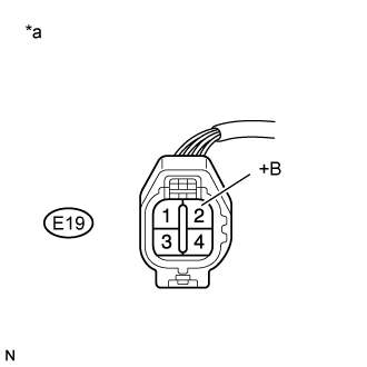 |
Disconnect the air fuel ratio sensor connector.
-
Turn the ignition switch to ON.
-
Measure the voltage according to the value(s) in the table below.
- Standard Voltage:
-
Tester Connection Switch Condition Specified Condition E19-2 (+B) — Body ground Ignition switch ON 11 to 14 V
Text in Illustration
*a Front view of wire harness connector(to Air Fuel Ratio Sensor)
|
|
||||
| OK | |
| 3.CHECK HARNESS AND CONNECTOR (AIR FUEL RATIO SENSOR — ECM) |
-
Disconnect the air fuel ratio sensor connector.
-
Disconnect the ECM connector.
-
Measure the resistance according to the value(s) in the table below.
- Standard Resistance:
-
Tester Connection Condition Specified Condition E19-1 (HA1A) — E26-23 (HA1A) Always Below 1 Ω E19-1 (HA1A) or E26-23 (HA1A) — Body ground Always 10 kΩ or higher
|
|
||||
| OK | |
| 4.CHECK WHETHER DTC OUTPUT RECURS (DTC P0031, P0032 OR P101D) |
-
Connect the intelligent tester to the DLC3.
-
Turn the ignition switch to ON.
-
Turn the tester on.
-
Clear the DTCs (Click here).
-
Turn the ignition switch off and wait for at least 30 seconds.
-
Turn the ignition switch to ON.
-
Turn the tester on.
-
Drive the vehicle in accordance with the driving pattern described in Confirmation Driving Pattern.
-
Enter the following menus: Powertrain / Engine and ECT / DTC.
-
Read the DTCs.
Result
Result Proceed to DTC is not output A DTC P0031, P0032 or P101D is output B
|
|
||||
| A | |
|
| 5.CHECK HARNESS AND CONNECTOR (AIR FUEL RATIO SENSOR — NO. 1 INTEGRATION RELAY) |
-
Disconnect the air fuel ratio sensor connector.
-
Remove the No. 1 integration relay from the engine room relay block and junction block assembly.
-
-
Measure the resistance according to the value(s) in the table below.
- Standard Resistance:
-
Tester Connection Condition Specified Condition E19-2 (+B) — 1A-7 Always Below 1 Ω E19-2 (+B) or 1A-7 — Body ground Always 10 kΩ or higher
|
|
||||
| OK | |
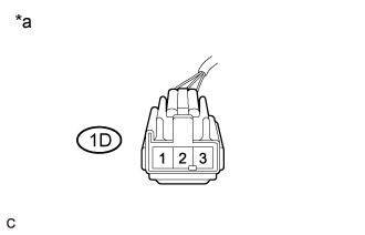
| 6.CHECK TERMINAL VOLTAGE (POWER SOURCE OF NO. 1 INTEGRATION RELAY) |
 |
Remove the No. 1 integration relay from the engine room relay block and junction block assembly.
-
Measure the voltage according to the value(s) in the table below.
- Standard Voltage:
-
Tester Connection Condition Specified Condition 1D-1 — Body ground Always 11 to 14 V
Text in Illustration
*a Front view of wire harness connector(to No. 1 Integration Relay)
|
|
||||
| OK | |
|
Ошибка P0031 Toyota – низкое напряжение цепи управления подогревателя ДК
4 года ago AutoTime
8 595
Ошибка P0031 Toyota — низкое напряжение цепи управления подогревателя датчика кислорода
P0031 Toyota код неисправности OBD-II: низкое напряжение цепи управления подогревателя датчика кислорода (A/F сенсор) (датчик 1 банка 1)
Расшифровка кода неисправности для автомобилей Nissan: низкое напряжение подогревателя датчика кислорода (HO2S) 1 Банк 1
Что означает ошибка P0031 Toyota
Этот код ошибки представляет собой общий код неисправности. Он применяется ко всем автомобилям Toyota, оснащенным OBD-II. Этапы диагностики и ремонта могут варьироваться в зависимости от модели автомобиля.
Эта ошибка говорит о том что, цепь подогревателя лямбда-зонда имеет низкое напряжение. Подогреватель датчика кислорода необходим для правильного контроля выхлопа во время запуска и прогрева двигателя, когда он холодный.
Причины кода P0031 Toyota?
Если после того как, ошибка была сброшена она появляется вновь, то проблема находится в первом верхнем лямбда -зонде. В датчике может выйти из строя подогреватель, он может иметь плохой (окисленный) контакт, неисправный 12-вольтовый вход или проблему в разъеме. Очень редко, но источником ошибки бывает неисправность блока управления двигателем Toyota.
Причины ошибки:
‘);
instant= new adsenseLoader( ‘#quads-ad4-place’, {
onLoad: function( ad ){
if (ad.classList.contains(«quads-ll»)) {
ad.classList.remove(«quads-ll»);
}
}
});
}if ( quads_screen_width >= 1024 && quads_screen_width
‘);
instant= new adsenseLoader( ‘#quads-ad4-place’, {
onLoad: function( ad ){
if (ad.classList.contains(«quads-ll»)) {
ad.classList.remove(«quads-ll»);
}
}
});
}if ( quads_screen_width >= 768 && quads_screen_width
Что необходимо ремонтировать при этой ошибке?
Наиболее распространенными местами для ремонта при этом коде DTC являются:
- электропроводка, которая повреждается чрезмерным теплом от выхлопных газов. Убедитесь, что проводка не имеет повреждений, на датчик поступает правильное напряжение и он имеет хороший контакт «земля».
При включенном зажигании и выключенном двигателе проверьте подачу напряжения +12 В на подогреватель сенсора. Если напряжение отсутствует, необходимо отремонтировать обрыв или короткое замыкание цепи, предварительно определив, необходимо ли заменить предохранитель если было короткое замыкание. - Если цепь питания не повреждена, необходимо снять цепь заземления с разъема проводки ECM и проверьте сопротивление на цепи. Если сопротивление бесконечное, необходимо восстановить контакт.
Если цепь управления проверена, то скорее всего неисправен датчик кислорода. - Необходимо заменить датчик и провести повторную диагностику.
CONFIRMATION DRIVING PATTERN
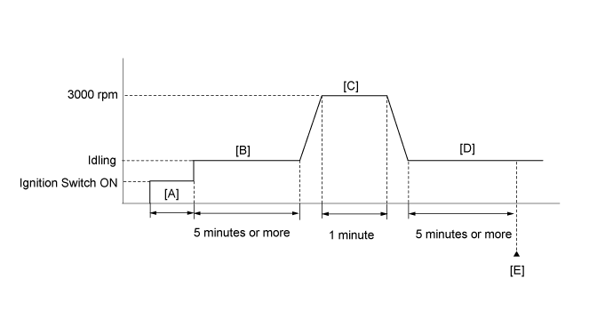
- Connect the intelligent tester to the DLC3.
- Turn the ignition switch to ON and turn the tester on.
- Clear the DTCs (even if no DTCs are stored, perform the clear DTC procedure).
- Turn the ignition switch off and wait for at least 30 seconds.
- Turn the ignition switch to ON and turn the tester on .
- Start the engine and idle it for 5 minutes or more .
- With the vehicle stationary, depress the accelerator pedal and maintain an engine speed of 3000 rpm for 1 minute .
- Idle the engine for 5 minutes or more .
- Enter the following menus: Powertrain / Engine and ECT / DTC .
- Read the pending DTCs.
- HINT:
- If a pending DTC is output, the system is malfunctioning.
- If a pending DTC is not output, perform the following procedure.
- Enter the following menus: Powertrain / Engine and ECT / Utility / All Readiness.
- Input the DTC: P0031, P0032 or P101D.
- Check the DTC judgment result.
Tester Display Description NORMAL - DTC judgment completed
- System normal
ABNORMAL - DTC judgment completed
- System abnormal
INCOMPLETE - DTC judgment not completed
- Perform driving pattern after confirming DTC enabling conditions
N/A - Unable to perform DTC judgment
- Number of DTCs which do not fulfill DTC preconditions has reached ECU memory limit
- HINT:
- If the judgment result shows NORMAL, the system is normal.
- If the judgment result shows ABNORMAL, the system has a malfunction.
- If the judgment result shows INCOMPLETE or N/A, perform steps through again.
На каких автомобилях чаще встречается данная проблема
Проблема с кодом P0031 может встречаться на различных машинах, но всегда есть статистика, на каких марках эта ошибка присутствует чаще. Вот список некоторых из них:
- Audi
- BMW
- Chevrolet (Шевроле Авео, Круз)
- Chrysler (Крайслер ПТ Крузер)
- Citroen (Ситроен С4)
- Daewoo (Дэу Нексия)
- Dodge (Додж Караван, Рам)
- Ford (Форд Фиеста, Фокус, Фьюжн)
- Honda
- Hyundai (Хендай Санта фе, Солярис)
- Infiniti (Инфинити fx35)
- Jeep (Джип Вранглер, Гранд Чероки)
- Kia (Киа Рио, Соренто)
- Lexus (Лексус gs300, gx470, is250, rx350)
- Lifan (Лифан х60)
- Mazda (Мазда 3, Мазда 6, Мазда cx7, Демио, MPV)
- Mercedes
- Mitsubishi (Митсубиси Аутлендер, Галант, Лансер)
- Nissan (Ниссан Альмера, Альтима, Кашкай, Мурано, Ноут, Примера, Теана, Х-Трейл)
- Peugeot (Пежо 207, 308)
- Renault (Рено Колеос)
- Skoda (Шкода Октавия, Фабия)
- Subaru (Субару Аутбек, Импреза, Легаси, Трибека, Форестер)
- Suzuki (Сузуки Витара, Джимни, Гранд Витара, Лиана, Свифт)
- Toyota (Тойота Авенсис, Аллион, Камри, Королла, Ленд Крузер, Марк 2, Прадо, Премио, Приус, Рав4, Хайс, Ярис)
- Volkswagen (Фольксваген Гольф, Поло Седан)
- Volvo
- ВАЗ 2114
- Лада Калина, Нива, Приора
С кодом неисправности Р0031 иногда можно встретить и другие ошибки. Наиболее часто встречаются следующие: P0030, P0032, P0037, P0038, P0051, P0052, P0057, P0108, P0123, P0218, P0444, P0445, P0714, P0753, P1598, P1684.
DESCRIPTION
Refer to DTC P2195 (Click here).
- HINT:
- When any of these DTCs is stored, the ECM enters fail-safe mode. The ECM turns off the air fuel ratio sensor heater in fail-safe mode. Fail-safe mode continues until the ignition switch is turned off.
- Although the DTC titles say oxygen sensor, these DTCs relate to the air fuel ratio sensor.
- Sensor 1 refers to the sensor mounted in front of the three-way catalytic converter and located near the engine assembly.
-
The ECM has a pulse width modulated control circuit to adjust the current through the heater. The air fuel ratio sensor heater circuit uses a relay on the +B side of the circuit.
| DTC No. | DTC Detection Condition | Trouble Area |
| P0031 | Air fuel ratio sensor heater current is less than 0.8 A, even when the air fuel ratio sensor heater duty cycle is 30% or higher (1 trip detection logic). |
|
| P0032 | Air fuel ratio sensor heater current reaches the high limit(Hybrid IC high current limiter monitor input «Fail») (1 trip detection logic). |
|
| P101D | The heater current is higher than the specified value while the heater is not operating (1 trip detection logic). | ECM |
- HINT:
- Sensor 1 refers to the sensor closest to the engine assembly.
- Sensor 2 refers to the sensor farthest away from the engine assembly.