
CONFIRMATION DRIVING PATTERN
- Connect the intelligent tester to the DLC3.
- Turn the ignition switch to ON and turn the tester on.
- Clear the DTCs (even if no DTCs are stored, perform the clear DTC procedure).
- Turn the ignition switch off and wait for at least 30 seconds.
- Turn the ignition switch to ON and turn the tester on.
- Start the engine.
- Idle the engine for 10 seconds or more.
- Enter the following menus: Powertrain / Engine and ECT / DTC.
- Read the pending DTCs.
- HINT:
- If a pending DTC is output, the system is malfunctioning.
- If a pending DTC is not output, perform the following procedure.
- Enter the following menus: Powertrain / Engine and ECT / Utility / All Readiness.
- Input the DTC: P0365, P0367 or P0368.
- Check the DTC judgment result.
Tester Display Description NORMAL - DTC judgment completed
- System normal
ABNORMAL - DTC judgment completed
- System abnormal
INCOMPLETE - DTC judgment not completed
- Perform driving pattern after confirming DTC enabling conditions
N/A - Unable to perform DTC judgment
- Number of DTCs which do not fulfill DTC preconditions has reached ECU memory limit
- HINT:
- If the judgment result shows NORMAL, the system is normal.
- If the judgment result shows ABNORMAL, the system has a malfunction.
- If the judgment result shows INCOMPLETE or N/A, perform the Confirmation Driving Pattern and check the DTC judgment result again.
Диагностика и решение проблем
Проверьте двигатель или просмотрите историю техобслуживания автомобиля на предмет недавнего ремонта зубчатого ремня ГРМ. А также датчика распредвала или датчика коленчатого вала.
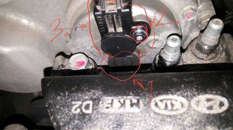
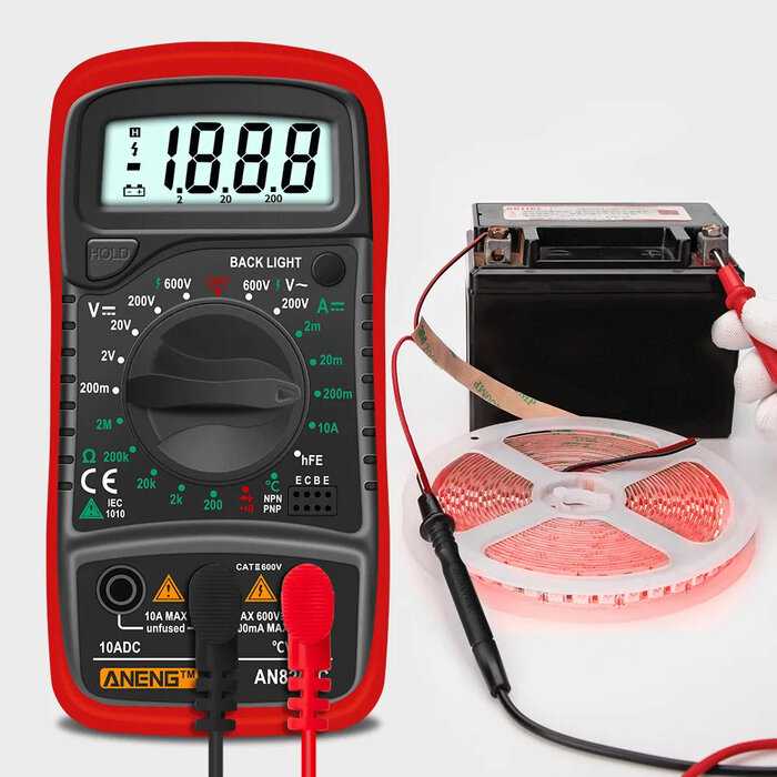
При выключенном зажигании снимите фишку с датчика распредвала. Включите зажигание и убедитесь, что тестер загорается между клеммой 1 цепи напряжения зажигания и заземлением.
Проверяем тестером, нет ли короткого замыкания на землю или обрыва/высокого сопротивления в цепи напряжения зажигания. Если проверка цепи пройдена и предохранитель цепи зажигания разомкнут. Проверьте все компоненты подключенные к цепи зажигания, и при необходимости замените их.
Подключить тестер между клеммой заземления 2 и клеммой напряжения зажигания 1. Убедиться, что тестер загорелся. Если тестер не загорается, проверьте цепь заземления на обрыв/высокое сопротивление.
Включите зажигание, проверьте 4,2-5,2 В между клеммой 3 сигнальной цепи и клеммой 2 цепи заземления. Если диапазон сигналов ниже указанного, проверьте цепь сигнала на короткое замыкание на землю или обрыв/высокое сопротивление. Убедитесь, что проверка цепи выполнена правильно и замените электронный модуль.
При значении выше указанного диапазона, проверьте цепь сигнала на наличие короткого замыкания на напряжение. Если проверка цепи выполнена правильно, замените электронный модуль.
Проверьте следующие условия, если до появления ошибки P0365 проводились ремонтные работы:
- Правильный монтаж датчика распредвала.
- Правильный монтаж датчика коленчатого вала.
- Проблема с натяжителем зубчатого ремня.
- Неправильно установленный ремень газораспределительного механизма.
- Прыжок зубьев звездочки через зубчатый ремень газораспределительного механизма.
- Зубчатое колесо коленчатого вала или ревматический датчик распредвала смещены из верхнего тупикового положения (TDC) на коленчатом валу.
На каких автомобилях чаще встречается данная проблема
Проблема с кодом P0365 может встречаться на различных машинах, но всегда есть статистика, на каких марках эта ошибка присутствует чаще. Вот список некоторых из них:
- Audi (Ауди а6)
- BMW
- Chevrolet (Шевроле Авео, Круз, Орландо)
- Dodge (Додж Джорней)
- Ford (Форд Мондео, Фокус)
- Honda (Хонда Пилот, Цивик)
- Hyundai (Хендай Санта фе, Соната)
- Kia (Киа Маджентис, Пиканто, Соренто, Спортейдж)
- Lexus
- Mercedes (Мерседес c200)
- Mitsubishi (Митсубиси Лансер)
- Nissan
- Opel (Опель Астра, Вектра, Зафира)
- Subaru (Субару Форестер)
- Toyota (Тойота Камри)
С кодом неисправности Р0365 иногда можно встретить и другие ошибки. Наиболее часто встречаются следующие: P000A, P0014, P0017, P0300, P0340, P0369, P2176.
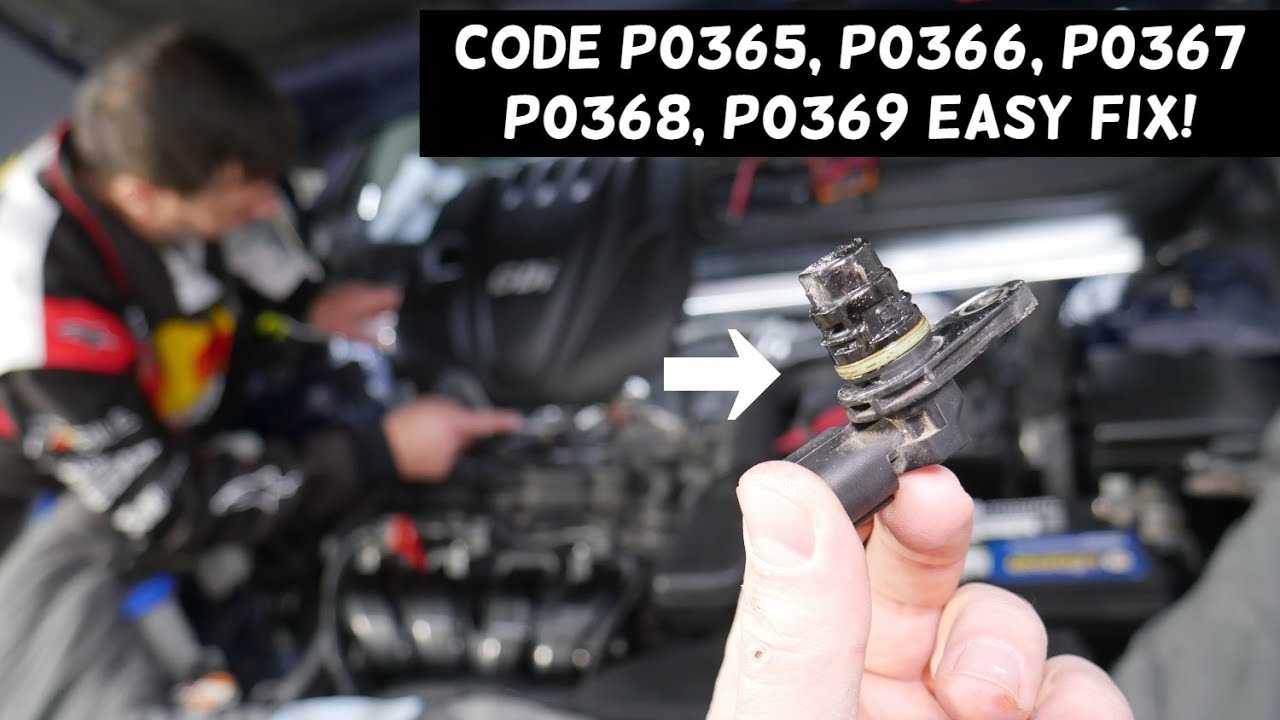
What Does Code P0365 Mean?
If a code P0365 accompanies a malfunction indicator lamp (MIL) in your vehicle, it means that the powertrain control module (PCM) has detected a problem with the exhaust camshaft position sensor (or circuit) for engine bank one. Bank 1 represents the bank of the engine that contains the number one cylinder. Sensor B indicates that the malfunction is occurring with the camshaft position sensor circuit that pertains to the exhaust camshaft.
The PCM uses input signals from the camshaft sensor/s and the crankshaft sensor to monitor the position and revolutions per minute (RPM) of these vital engine components, manage timing fluctuations, and map fuel delivery strategy. Clearly, variations in engine configuration will dictate the number of camshaft sensors that are required. For instance; an overhead valve engine will typically be equipped with a single camshaft sensor because the engine has only one camshaft. An overhead cam, four-cylinder engine will likely have only one camshaft sensor as well (because it has only one engine bank), but an overhead cam, V6 requires at least two camshaft sensors (one per engine bank). Likewise, a dual overhead cam, V8 engine will require four camshaft sensors because there are two engine banks with two camshafts in each bank.
Each camshaft sensor has a circuit (or circuits) dedicated to providing the PCM with individual input signal/s. Camshaft position and camshaft speed are compared to the speed and position of the crankshaft in order to prevent engine damage and calculate ignition timing and fuel delivery strategy. Since the camshaft/s turn at half the speed of the crankshaft, it is critical that the PCM is able to distinguish between engine intake and exhaust stokes (rotations). This is also accomplished with the camshaft position sensor.
The most common camshaft position sensor design utilizes an electromagnetic hall effect sensor positioned in very close proximity (usually only several thousandths of an inch) from a circuit completing engine ground. In most cases, either a reluctor ring (with precisely machined teeth) is affixed to the camshaft pulley or there are cogs stringently integrated into the camshaft itself.
The camshaft position sensor is mounted so that these teeth/cogs pass very closely to its magnetic end. As the camshaft rotates, the raised areas complete an electromagnetic circuit. When the indentations (between the teeth pass) pass the camshaft sensor, the circuit is briefly interrupted. Since the camshaft rotates very quickly, the process of repeatedly completing and interrupting the circuit occurs in milliseconds. This progression of completing and interrupting the camshaft position sensor circuit produces a waveform pattern. This pattern is recognized by the PCM as camshaft position. All of the camshaft position sensors and the crankshaft sensor function in a similar manner.
When the engine is running, the PCM constantly compares input signals from the camshafts and the crankshaft. If the camshaft position is not within a specified degree of variation from the crankshaft and other camshafts, under certain circumstances, for a set period of time, a P0365 code will be stored and a MIL may be illuminated.
Typically, when this code is set, the engine will continue to start and run but will fail to perform at an efficient level.
INSPECTION PROCEDURE
- HINT:
- Read freeze frame data using the intelligent tester. The ECM records vehicle and driving condition information as freeze frame data the moment a DTC is stored. When troubleshooting, freeze frame data can help determine if the vehicle was moving or stationary, if the engine was warmed up or not, if the air fuel ratio was lean or rich, and other data from the time the malfunction occurred.
- If no problem is found through this diagnostic troubleshooting procedure, there may be a mechanical problem with the engine.
| 1.CHECK TERMINAL VOLTAGE (POWER SOURCE OF CAMSHAFT POSITION SENSOR) |
 |
Disconnect the camshaft position sensor for exhaust camshaft connector.
-
Turn the ignition switch to ON.
-
Measure the voltage according to the value(s) in the table below.
- Standard Voltage:
-
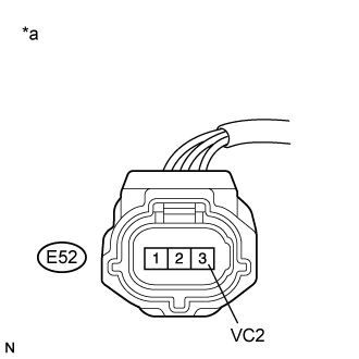
Tester Connection Switch Condition Specified Condition E52-3 (VC2) — Body ground Ignition switch ON 4.5 to 5.5 V
Text in Illustration
*a Front view of wire harness connector(to Camshaft Position Sensor for Exhaust Camshaft)
|
|
||||
| OK | |
| 2.CHECK HARNESS AND CONNECTOR (CAMSHAFT POSITION SENSOR — ECM) |
-
Disconnect the camshaft position sensor for exhaust camshaft connector.
-
Disconnect the ECM connector.
-
Measure the resistance according to the value(s) in the table below.
- Standard Resistance:
-
Tester Connection Condition Specified Condition E52-1 (VVE+) — E26-81 (EV1+) Always Below 1 Ω E52-2 (VVE-) — E26-112 (EV1-) Always Below 1 Ω E52-1 (VVE+) or E26-81 (EV1+) — Body ground Always 10 kΩ or higher E52-2 (VVE-) or E26-112 (EV1-) — Body ground Always 10 kΩ or higher
|
|
||||
| OK | |
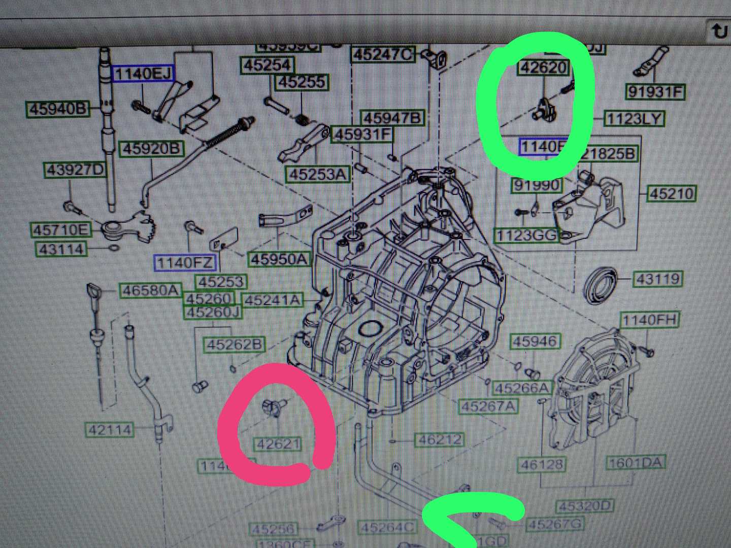
| 3.CHECK SENSOR INSTALLATION (CAMSHAFT POSITION SENSOR FOR EXHAUST CAMSHAFT) |
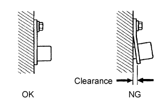 |
Check the camshaft position sensor for exhaust camshaft installation.
- OK:
- Camshaft position sensor is installed correctly.
|
|
||||
| OK | |
| 4.INSPECT EXHAUST CAMSHAFT (TIMING ROTOR) |
-
Check the timing rotor of the exhaust camshaft.
- OK:
- Camshaft timing rotor does not have any cracks or deformation.
- HINT:
- Perform «Inspection After Repair» after replacing the exhaust camshaft (Click here).
|
|
||||
| OK | |
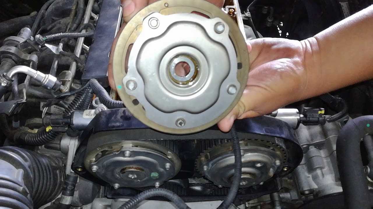
| 5.CHECK VALVE TIMING (CHECK FOR LOOSE TIMING CHAIN AND JUMPED TEETH) |
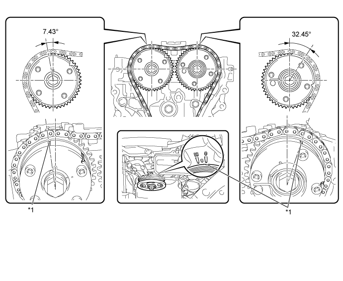
| *1 | Timing Mark | — | — |
-
Remove the cylinder head cover sub-assembly.
-
Turn the crankshaft pulley and align its groove with the «0» timing mark of the timing chain cover.
-
Check that the timing marks of the camshaft timing gear assembly and camshaft timing exhaust gear assembly are at the positions shown in the illustration.
- HINT:
- If the timing marks are not as shown, turn the crankshaft one revolution clockwise.
- OK:
- Timing marks on camshaft timing gear assembly and camshaft timing exhaust gear assembly are aligned as shown in the illustration.
|
|
||||
| OK | |
| 6.REPLACE CAMSHAFT POSITION SENSOR (FOR EXHAUST CAMSHAFT) |
-
Replace the camshaft position sensor (for exhaust camshaft) (Click here).
| NEXT | |
| 7.CHECK WHETHER DTC OUTPUT RECURS (DTC P0365, P0367 OR P0368) |
-
Connect the intelligent tester to the DLC3.
-
Turn the ignition switch to ON.
-
Turn the tester on.
-
Clear the DTCs (Click here).
-
Turn the ignition switch off and wait for at least 30 seconds.
-
Start the engine.
-
Turn the tester on.
-
Drive the vehicle in accordance with the driving pattern described in Confirmation Driving Pattern.
-
Enter the following menus: Powertrain / Engine and ECT / DTC.
-
Read the DTCs.
Result
Result Proceed to DTC P0365, P0367 or P0368 is output A DTC is not output B - HINT:
- If the engine does not start, replace the ECM.
|
|
||||
| A | |
|
| 8.CHECK HARNESS AND CONNECTOR (CAMSHAFT POSITION SENSOR — ECM) |
-
Disconnect the camshaft position sensor for exhaust camshaft connector.
-
Disconnect the ECM connector.
-
Measure the resistance according to the value(s) in the table below.
- Standard Resistance:
-
Tester Connection Condition Specified Condition E52-3 (VC2) — E26-111 (VCE1) Always Below 1 Ω E52-3 (VC2) or E26-111 (VCE1) — Body ground Always 10 kΩ or higher
|
|
||||
| OK | |
|
Что означает ошибка P0365
Ошибка P0365 указывает на то, что PCM автомобиля обнаружил неисправность в электрической цепи датчика “B” положения распределительного вала (банк 1). Датчик положения распределительного вала рассчитывает частоту вращения и положение распределительного вала и отправляет сигнал на модуль управления АКПП (PCM). PCM использует полученную информацию для управления впрыском топлива и моментом зажигания. Если PCM автомобиля обнаружит, что в течение нескольких секунд после запуска двигателя напряжение в цепи датчика является слишком низким, в его памяти сохранится ошибка P0365. Следует отметить, что отметка “B” указывает на то, датчик расположен на стороне выпуска головки блока цилиндров. Банк 1 означает, что датчик расположен на стороне двигателя, где находится цилиндр 1.

Диагностика и решение проблем
Проверьте двигатель или просмотрите историю техобслуживания автомобиля на предмет недавнего ремонта зубчатого ремня ГРМ. А также датчика распредвала или датчика коленчатого вала.
При выключенном зажигании снимите фишку с датчика распредвала. Включите зажигание и убедитесь, что тестер загорается между клеммой 1 цепи напряжения зажигания и заземлением.
Проверяем тестером, нет ли короткого замыкания на землю или обрыва/высокого сопротивления в цепи напряжения зажигания. Если проверка цепи пройдена и предохранитель цепи зажигания разомкнут. Проверьте все компоненты подключенные к цепи зажигания, и при необходимости замените их.
Подключить тестер между клеммой заземления 2 и клеммой напряжения зажигания 1. Убедиться, что тестер загорелся. Если тестер не загорается, проверьте цепь заземления на обрыв/высокое сопротивление.
Включите зажигание, проверьте 4,2-5,2 В между клеммой 3 сигнальной цепи и клеммой 2 цепи заземления. Если диапазон сигналов ниже указанного, проверьте цепь сигнала на короткое замыкание на землю или обрыв/высокое сопротивление. Убедитесь, что проверка цепи выполнена правильно и замените электронный модуль.
При значении выше указанного диапазона, проверьте цепь сигнала на наличие короткого замыкания на напряжение. Если проверка цепи выполнена правильно, замените электронный модуль.
Проверьте следующие условия, если до появления ошибки P0365 проводились ремонтные работы:
- Правильный монтаж датчика распредвала.
- Правильный монтаж датчика коленчатого вала.
- Проблема с натяжителем зубчатого ремня.
- Неправильно установленный ремень газораспределительного механизма.
- Прыжок зубьев звездочки через зубчатый ремень газораспределительного механизма.
- Зубчатое колесо коленчатого вала или ревматический датчик распредвала смещены из верхнего тупикового положения (TDC) на коленчатом валу.
Техническое описание и расшифровка ошибки P0340
Этот диагностический код неисправности (DTC) является общим кодом силового агрегата. Ошибка P0365 считается общим кодом, поскольку применяется ко всем маркам и моделям транспортных средств (на 1996 год и новее). Хотя конкретные этапы ремонта могут несколько отличаться в зависимости от модели.
Этот код указывает на то, что была обнаружена проблема в цепи датчика «В» положения распредвала (Банк 1). Так как речь идет о цепи, это означает, что проблема может лежать в любой части цепи (самом датчике, проводке или ЭБУ). Поэтому неисправность не всегда кроется в самом датчике положения распределительного вала.